
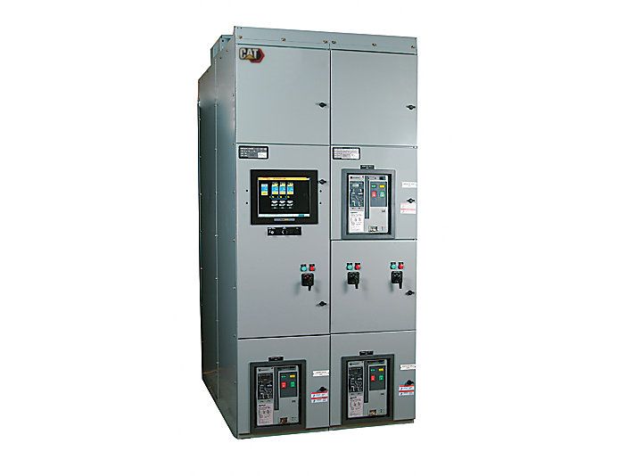
Cat EGP Switchgear
Caterpillar offers standard Switchgear products, which can support a wide variety of applications, or provide a custom designed system to meet your specific project needs. The Emergency Generator paralleling (EGP) product supports paralleling on an isolated generator bus and is commonly used in prime power or emergency standby systems. Caterpillar Standard Switchgear products provide a solution able to combine all elements of monitoring and control for Caterpillar generator sets in a single-source package. Caterpillar also designs and manufacturers custom switchgear to meet specific customer requirements and functionality.
Product Images
Product Videos
Virtual Product Tour (VPT)
Specifications
| Name | Type | Value | Unit Value (Imperial) | Unit Name | Unit Value (Metric) | Unit Name (Metric) |
|---|---|---|---|---|---|---|
| Configuration | text | Configurable PLC based switchgear capable of controlling and monitoring multiple generator sets, tie and load breakers in conjunction with downstream transfer switches for standby or emergency applications | ||||
| Modes of Operation | text | Multi-unit Island and multi-unit standby mode with optional redundant controls and components. | ||||
| Application | text | LV and MV (208V - 38 kV) |
Documents & Spec Sheets
Features & Benefits
EGP Switchgear
- High Speed Supervisory Network
- Automatic Start/Stop
- Automatic “Dead Bus” Coordination
- Programmable Load Shed / Load Add Functions
- Networked Engine Communications
- Generator Protection
- Engine Tuning
- Mode Selection
- Selectable Auto/ Manual Control
- Password Protection for Protective Settings and Setup
- Load/No Load Test
- Touch Screen (HMI) Display
- NFPA 99/110 Compliant Alarm
- Annunciation with Audible Horn
- Engine Control mimic Screen with gauges for RPM, DC Battery Voltage oil Pressure, Engine Coolant temperature, Engine Hours, Number of starts
Complete Specifications
Technical Summary
| Name | Type | Value | Unit Value (Imperial) | Unit Name | Unit Value (Metric) | Unit Name (Metric) |
|---|---|---|---|---|---|---|
| Configuration | text | Configurable PLC based switchgear capable of controlling and monitoring multiple generator sets, tie and load breakers in conjunction with downstream transfer switches for standby or emergency applications | ||||
| Modes of Operation | text | Multi-unit Island and multi-unit standby mode with optional redundant controls and components. | ||||
| Application | text | LV and MV (208V - 38 kV) | ||||
| ANSI Protective Devices | text | 15/25, 27/59, 81 O/U, 32, 40, 50, 51 | ||||
| Certifications | text | IBC, CBC, UBC & OSHPD Certified | ||||
| Control Panel Enclosure | text | NEMA 1 or NEMA 3R Freestanding Construction | ||||
| Operating Temperature | text | 0°C to 50°C | ||||
| Storage Temperature | text | -20°C to +60°C | ||||
| Low Voltage Standards | text | NEMA SG-5, CSA, ANSI C37.51, ANSI C37.20.1, UL 1558 or UL 891, NFPA 110, NFPA 99 and NFPA 70 | ||||
| Medium Voltage Standards | text | NEMA SG-5, ANSI / IEEE C37.20.2, CSA-C22.2 No. 31-M89, EEMAC G8-3.2, NFPA 70, NFPA 99 and NFPA 1110 |
Standard Equipment
EGP Switchgear
- Choice of 19” Surface Acoustic Wave Color or 15” Resistive Color Touchscreen
- Emergency Stop Button for each generator
- Instant Auto Switch
- Generator Demand Priority Control
- Audible Alarm & Horn Silence Button
- Circuit Breaker Control Switch with Indicators
Optional Equipment
Data Table Interface
- * Accomodates interface with a building management system for monitoring all system parameters via Modbus RTU or TCP
Supplemental Hardware Synchronization check relay (ANSI 25 Device)
Supplemental Hardware Synchronization check relay (ANSI 25 Device)
Supplemental Hardware Synchronization check relay (ANSI 25 Device)
Supplemental Hardware Synchronization check relay (ANSI 25 Device)
Supplemental Hardware Synchronization check relay (ANSI 25 Device)
Supplemental Hardware Synchronization check relay (ANSI 25 Device)
Supplemental Hardware Synchronization check relay (ANSI 25 Device)
Supplemental Hardware Synchronization check relay (ANSI 25 Device)
Supplemental Hardware Synchronization check relay (ANSI 25 Device)
Supplemental Hardware Synchronization check relay (ANSI 25 Device)
Supplemental Hardware Synchronization check relay (ANSI 25 Device)
- * Provides additional discrete synchronization protection
Supplemental Hardware Synchronization check relay (ANSI 25 Device)
Supplemental Hardware Synchronization check relay (ANSI 25 Device)
Supplemental Hardware Synchronization check relay (ANSI 25 Device)
Supplemental Hardware Synchronization check relay (ANSI 25 Device)
Supplemental Hardware Synchronization check relay (ANSI 25 Device)
Remote Power Monitoring System
- * To monitor breaker status, alarms, metering and other operating parameters