
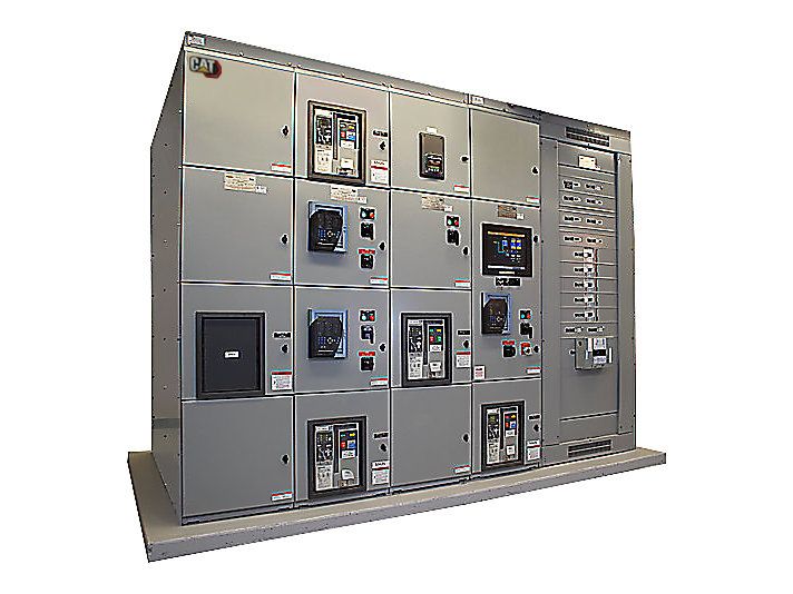
Cat XLM Switchgear
The Emergency Transfer and Load management (XLM) gen switchgear supports transfer between the utility source and generator bus and allows for sustained parallel operation with the utility for load management applications.
Product Images
Product Videos
Virtual Product Tour (VPT)
Specifications
| Name | Type | Value | Unit Value (Imperial) | Unit Name | Unit Value (Metric) | Unit Name (Metric) |
|---|---|---|---|---|---|---|
| Configuration | text | Configurable PLC based switchgear capable of controlling and monitoring multiple generator sets, tie, utility and load breakers for utility paralleling applications | ||||
| Modes of Operation | text | Emergency Standby, Utility Import/Export, Peak shaving, and base load operations with redundant controls and components. Closed transition to/from generator power | ||||
| Application | text | LV and MV ( 208V - 38 kV |
Documents & Spec Sheets
Cat XLM Switchgear
DownloadCat® Extended Service Coverage (ESC)
DownloadEMCP 4.4 Master Control Panel XLM Configuration
DownloadTech-Link Switchgear Remote Access System Service Tool
DownloadParalleling Switchgear Application & Installation Guide
DownloadCat® Switchgear Advanced GUI / HMI Operator Interface
DownloadFeatures & Benefits
XLM Switchgear
- High Speed Supervisory Network
- Automatic Start/Stop
- Automatic “Dead Bus” Coordination
- Automatic Power Factor Control when in Parallel with Utility Power
- Programmable Load Shed / Load Add Functions
- Networked Engine Communications
- Generator & Utility Protection
- Engine Tuning
- Mode Selection
- Selectable Auto/ Manual Control
- Password Protection for Protective Settings and Setup
- Load/No Load Test
- Touch Screen (HMI) Display
- NFPA 99/110 Compliant Alarm
- Annunciation with Audible Horn
- Engine Control mimic Screen with gauges for RPM, DC Battery Voltage, Oil Pressure, Engine Coolant temperature, Engine Hours, Number of starts
Complete Specifications
Technical Summary
| Name | Type | Value | Unit Value (Imperial) | Unit Name | Unit Value (Metric) | Unit Name (Metric) |
|---|---|---|---|---|---|---|
| Configuration | text | Configurable PLC based switchgear capable of controlling and monitoring multiple generator sets, tie, utility and load breakers for utility paralleling applications | ||||
| Modes of Operation | text | Emergency Standby, Utility Import/Export, Peak shaving, and base load operations with redundant controls and components. Closed transition to/from generator power | ||||
| Application | text | LV and MV ( 208V - 38 kV | ||||
| ANSI Protective Devices | text | 15/25, 27/59, 81 O/U, 32, 40, 50, 51 | ||||
| ANSI Protective Devices | text | 15/25, 27/59, 81 O/U, 32, 40, 47, 50, 51, 86 | ||||
| Certifications | text | IBS, CBC, UBC & OSHPD Certified | ||||
| Control Panel Enclosure | text | NEMA 1 or NEMA 3R, Freestanding Construction | ||||
| Operating Temperature | text | 0 degrees to 50 degrees C | ||||
| Storage Temperature | text | -20 degrees C to +60 degrees C | ||||
| Low Voltage Standards | text | NEMA SG-5, CSA, ANSI C37.51, ANSI C37.20.1, UL 1558 or UL 891, NFPA 110, NFPA 99 and NFPA 70 | ||||
| Medium Voltage Standards | text | NEMA SG-5, ANSI / IEEE C37.20.2, CSA-C22.2 No. 31-M89, EEMAC G8-3.2, NFPA 70, NFPA 99 and NFPA 1110 |
Standard Equipment
Generator Demand Priority Control
- Automatically match the on-line generator capacity to the loads, and avoid unnecessary operation of generator sets.
Optional Equipment
Data Table Interface
- Accommodates interface with a building management system for monitoring all system parameters via Modbus RTU or TCP
Supplemental Hardware Synchronization check relay (ANSI 25 Device)
Supplemental Hardware Synchronization check relay (ANSI 25 Device)
Supplemental Hardware Synchronization check relay (ANSI 25 Device)
Supplemental Hardware Synchronization check relay (ANSI 25 Device)
Supplemental Hardware Synchronization check relay (ANSI 25 Device)
Supplemental Hardware Synchronization check relay (ANSI 25 Device)
Supplemental Hardware Synchronization check relay (ANSI 25 Device)
Supplemental Hardware Synchronization check relay (ANSI 25 Device)
Supplemental Hardware Synchronization check relay (ANSI 25 Device)
Supplemental Hardware Synchronization check relay (ANSI 25 Device)
Supplemental Hardware Synchronization check relay (ANSI 25 Device)
- Provides additional discrete synchronization protection
Supplemental Hardware Synchronization check relay (ANSI 25 Device)
Supplemental Hardware Synchronization check relay (ANSI 25 Device)
Supplemental Hardware Synchronization check relay (ANSI 25 Device)
Supplemental Hardware Synchronization check relay (ANSI 25 Device)
Supplemental Hardware Synchronization check relay (ANSI 25 Device)
Supplemental Hardware Synchronization check relay (ANSI 25 Device)
Supplemental Hardware Synchronization check relay (ANSI 25 Device)
Remote Power Monitoring System
- To monitor breaker status, alarms, metering and other operating parameters